Monday, June 10, 2013

Weeks 9,10 &11

Summary of Task Completed

  • Complete the Solidworks 3d modeling
  • Researched different methods of constructing mounting brackets
  • Designed and fabricated 4 types of CNC milled brackets 
  • Create interactive pdf

Project Development


After reviewing our major milestones the group got together to discuss what tasks had to be competed in order to achieve our goals, as there is only a third of the semester remaining. Our goals have changed quite significantly in what we plan to present as our final  output, as we have continually adapted as we continue to learn and find out the best methods of achieving a high result. The main tasks that I have been given were to fix up my Oil Filter model - as I had problems assembling it correctly in Solidworks - and then move on to researching and developing several mounting bracket options that we could use for our hybrid motorcycle. 

Complete Solidworks modeling - Oil Filter Fix


The major problem that I encountered with the oil filter is that I was unable to combine and subtract the fins within the inside of the cylindrical object. I realized that this was because I created each component as its own part and then used an "assembly" to put it all together. By experimenting with various methods and tools in Solidworks I eventually found that by placing all of the parts into a single Part file I could achieve the desired goal. 


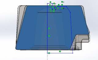
The image below shows the result of modeling the features as separate parts and then placing each part within an Assembly file to construct the Oil FIlter. Although this method seems the most logical, as it allows for greater accuracy with placement of each finn, I could not find a tool that would allow me to subtract the finns mass within the cylindrical part.


 To fix this I replicated the cylindrical part and placed it in exactly the same position although within the same sketch as each individual finn. This provided me with a "ghost" of where the finn must be cut (mass removed) in order for it to sit flush with the exterior skin of the cylindrical part (image 2). 

image 1 -Shaded blue part is the finn. The blue outline is the overall extents of the finn after removing the mass within the cylinder up to its exterior skin. 
image 2 - The blue outline sketch shows the "ghost" cylinder that must be Cut-removed from the finn. 
image 3 - The shaded dark grey shows the finn after the mass has been removed.

image 4 - Inaccuracies start to occur using this method.
image 5 - the final product - problem solved!

Although this method allowed me to create the desired outcome, I still do not believe it is the best way of modeling. This is because often when adjusting the "ghost" sketch to ensure it removes the right amount of finn - so that the finn sits flush with the exterior skin of the cylinder - it is a matter of experimentation and constant adjustments. This can lead to an inaccurate model and also often can be quite deceptive as from one viewing angle the finn may look as though it is sitting flush, from another however there can often be a gap (image 4). 


Researching Engine Plate designs 


Researching the different methods of manufacturing engine plates was a lot more difficult then we initially anticipated. As we have no experience or knowledge on what engine plates are suitable we split the tasks into 3 categories (CNC milling, cast alumium and tubing).


Engine Plate Designs


Establishing the mounting positions within the frame

900 x600mm sheet to be sent to the lasercutter to have our prototype plates made.
During the first phase  of design I printed out a 1:1 CAD drawing of the Honda engine within the Norton frame to establish mounting positions and ensure everything was accurately placed.


research references

research references


Prototype lasercut plates made from 6mm Acrylic.


Create interactive pdf


The interactive pdf is a tool that as a group we thought would be the best way to present our models to a wider audience of hybrid motorcycle lovers as well as anyone who may be interested in our work. I took on the responsibility of getting this made and although I had never made an interactive pdf before, I found it quite simple to make. Following brief tutorials online I first created all of the necessary pages in a single indesign fileand then used Acrobat Pro to embed the interactivity. 

The main features I wanted to include within the pdf were;
- The 3d solidworks models; The aim was to embed the 3d Solidworks models that each group member had created throughout the semester of the honda and norton motorbike, so that viewers can rotate, zoom and view the models however they please. This feature also allows for various types of rendering views and the ability to measure the models whilst in the pdf. This can therefore become very useful for viewers who, whilst constructing there own hybrid motorcycles, can check measurements as a tool for reference. 
- 2d CAD drawings; Although we could not place the actual CAD files within the pdf, we did create a sheet for each model part that contained measured drawings in response to the 3d model. 
- Renders: Each model parts page also contained a simple render of the part with its designated material. This was not 100% necessary although we thought that it tied everything together quite nicely. 
- URL Links; Additionally, the pdf also provided a quick insight into getting prototypes made for things such as the engine plates and provided links to professionals that could have these prototypes constructed. 
- Wiki link; The pdf also has a link back to you wiki site and more specifically the e-resources page were viewers can download all of our models in a number of different file types for there own benefit. 


Limitations with interactive pdf;
- One major limitation with our interactive pdf was the inability to embed our grasshopper file. This was something that we knew would be impossible as the file type is too different, however if this was something that could be done, I believe it would have had a much greater impact on the overall successfulness of the pdf. 

Friday, May 3, 2013

Week 8 - Group and Individual Milestones

Group Performance
 
When beginning this task we outlined the main goals we wanted to accomplish as a group in the completion of this project. These goals consisted of;
  1. Developing a hybrid motorcycle by embedding a 1972 Honda CB750 motorbike engine within a Norton Featherbed Slimline frame.
  2. Establishing a new industry standard for file sharing and access to an extensive resource of accurate 3d motorcycle models, a documented account of our custom build which includes videos, photos and interactive animations, as well as a link to the wider motorcyle community, using the Honda CB750 and Norton Featherbed Frame as an example.  
As no members of our group had ever been involved in a project like this, nor had anyone known a lot of information about motorcycles, we decided to formulate tasks on a weekly basis depending on what we felt needed to be done to progress to the next stage of development. 

Below I have created a gantt chart to show our development of weekly tasks and what we aim to complete in the weeks to come.


The use of a clear communication strategy and agile developmental approach has been critical to the success of our group work this semester. Although a lot of the time the weekly tasks that we have set ourselves have taken longer than expected, the overall progress of the group has continued at a desired rate. The first few weeks of semester involved a large amount of learning as none of our group had any motorcycle experience, modelled 3d objects in Solidworks or developed a wikispace before. Now that we are all well into the swing of things we are at a point were we need to really push on our progress and aim high in terms of what we want to present for the final presentation.

Over the next few weeks we are going to have to develop a prototype for some functional new brackets that will be welded to the Norton frame holding the Honda engine inside. This is a big challenge and something we are going to need to spend time getting right. Our group dynamic seems to be working effectively so as long as we keep our mind on the tasks at hand we should be able to achieve our goals of designing, prototyping and getting quotes for a brakcet that can be completely functional in holding the engine within the frame.
 

Individual Performance

Each week every group member has been given tasks to complete to help in the progression of our overall project. The tasks that I have been assigned to include;
 
In completing these tasks I feel that I have helped our group in achieving the progress that we set ourselves consequently arriving at the strong position that we are in today to finish our project aims within the expected timeframe.  

Overall, I am most proud of my progress in 3D modelling. As Solidworks was a new modelling program for me at the beginning of the semester, I am proud of my progress and I feel that I am at a high standard of modelling capability.

Although at times throughout the semester I have been unable to complete the weekly tasks within the time frame originally set, I feel that these things were expected as we were dealing with unfamiliar challenges. Going forward I believe I can be very beneficial to the group in designing the new motorbike brackets as well as getting them manufactured as I have done similar tasks when undergoing Industrial design tasks in a previous degree.


Check out our wiki progress at: www.shadesofblack.wikispaces.com

Wednesday, May 1, 2013

Week 7 - Presentation week

This week our group did our Communication presentation which included a written speech, 3 minute video and prezi presentation. Unfortunately I had some personal issues which prevented my from being at University. However I was told from the group members that the markers were very pleased with out research and final output. Here is what my team mates presented;

Communication
For effective communication in a group project environment there are certain factors which need to be considered, including platforms, resources, HR, skills, roles, limitations, longevity etc in order to create an effective work environment and successful result.


Communication Strategies


In a typical hierarchical working relationships there are defined and independent communication paths between a leadership role and worker. For a collaborative environment it is essential to implement a cross-communicational team strategy. Within-team communication provides members with information about what their teammates are working on and where they are up to in the project development. When decisions and outcomes depend on the integration of different team member contributions it is important to be familiar with the tasks of fellow team mates to ensure a collaborative and comprehensive end result. This is particularly important for small teams or teams working with constantly changing environments or poorly defined outcomes (Fussell, S. 1998); something in which our group faces with roles and responsibilities continually being assessed and redefined throughout the project. It is therefore even more essential for us to focus on communicating directly to one another and include all participants in communication processes in order to achieve a successful outcome. Our group has achieved this style of communication by having many face-to-face meetings and setting up group communication platforms such as Facebook and Dropbox.

This type of group communication leads to increased passive awareness. "Passive awareness of what other team members are doing, provided by indirect participation in a communicative exchange...should enable a team member to better coordinate his/her activities with the rest of the team." (Fussell, S. 1998, p2) - Though this inter-team awareness is an important when dealing with a project such as ours it can also result in information overload; passive awareness consumes more of each individuals time and indirectly adds to an individual's work load. We face this problem on our Facebook group, were some posts are irrelevant to certain team members (e.g. querying measurements on a particular part of the bike that you are not working on). Using this type of team communication strategy lends to the group spending a lot of time on discussing ideas, concepts and solutions than actually implementing them.


Platforms

There are many methods of communication but for the context of our project we are looking at written communication, oral communication, face-to face and communication through media.

The benefits of written form is that as a team we have a physical record and reference of everything that was mentioned during discussion, these record also serve as evidence to avoid miscommunication or arguments amongst members in the future. Written communication can also avoid mistakes which can be made in interpreting other forms of communication (e.g. verbal)as it is a clearly defined communication medium.

Oral communication methods are also essential for teamwork, as members can provide and respond to each other’s feedback quickly and the issues and conflicts that occurred throughout the process of the project can be resolved through talking. Oral communication encourages flexibility as the method we have chosen to manage our team is one of Agile Development and therefore being able to communicate verbally helps us to understand each other’s idea's with greater understanding.

A face-to-face communication method directly corresponds with oral communication. This method is the most effective medium and has the greatest ability to communicate convince. Externally, face-to-face communication offers the opportunity to engage with our targeted audiences, creating a two-way relationship that enables the ability for audiences to respond.

Perhaps the most powerful source of communication is social media; a form of networking which has the ability to reach the mass market with only a minimal input. The media world is limitless and is vitally important to our project as there is such dispersed target audience (Bikers & CAM enthusiasts). Social media offers the opportunity for anyone to comment, edit and embellish on our resources, enabling open dialogue and interaction between project and audiences.


Responsibilities

Design teams commonly include members from different design disciplines that must integrate their individual specialised knowledge in order to effectively and efficiently produce professional design solutions. Communication, including the integration of inter disciplinary specialised knowledge, has developed into a fundamental aspect of the collaboration design process. Individual team members have specific roles and responsibilities in ensuring that the communication process remains fluent and allows for the exchange of information and conflict resolution.


Team leaders represent a significant component in the team design and communication process. The ability of the team leaders to communicate the direction and the organisational structure of the design team is vital to the success of the collaboration process. Design teams are increasingly required to work collaboratively in complex and dynamic environments which force them to constantly develop new team organisational structures and communication strategies. Team Leaders need to be able to adapt their communicational strategies to overcome challenges and obstacles in these dynamic team environments. The team leader’s main responsibilities during the team communication process include the communication of team goals, direction and culture, communicating project requirements and time schedules through division of individual tasks for completion and advising each team member of new decisions and resolving any issues arising from a communication breakdown.


Team members need to be able to integrate their individual roles and responsibilities for the collective success of the design collaborative team. A common cause of failure for design teams is the inability to communicate the coordination of individual team member contributions to the given project. The roles and responsibilities of each team member will depend on a number of factors including the project requirements and their individual design discipline background. Although the main roles and responsibilities of each team member will differ from project to project. There are still a number of common responsibilities that are common to all projects which involve the team member having to communicate. These usually include the need for team members to communicate their individual knowledge, abilities and skills to both other team members and the team leadership, communicate constructive feedback on current team work and progress.


Communication Longevity

Communication plays a critical role in terms of keeping the project moving forward and the ongoing longevity of the project. Internal communication is vital as it allows team members to come together and keep them on target towards future goals within an allocated time frame. Without these small individual steps being taken, groups will struggle to finish their goal with higher quality work.


To keep work focussed on the target audience teams must have a way of communicating externally with their target market. Some people may do this face to face, others through oral communication or even through an online forum. Having this form of communication with a reliable external source allows groups to gain first-hand knowledge from within the market itself.


Project Black is already looking beyond our group project, and how we can continue to develop our work for the future. As a group we have developed a wiki, whereby as both individuals and a team we are able to provide concise data to our target audience through the use of 3D models, analytical drawings and deconstruction videos. The space is a collection of data that provides not only the Honda CB750 community but also the motorcycle community as a whole, with a place to communicate, further their understanding or display jobs that are currently in progress or have been complete.

  • 7 Images


GDNet Structuring your research 2013 [online], Available from: https://depot.gdnet.org/cms/gallery27-iStock_000005622581Medium.jpg [Accessed: 18.4.2013]


Wallpapers – 3D Business People, LORDOFDESIGN, viewed 17 April 2013, < http://lordofdesign.com/wp-content/uploads/2010/03/Wallpapers-3D-Business-People.jpg>


How to Use the Law of Attraction with Goal Setting, Bowen, D, viewed on the 19/04/13 <http://www.empowernetwork.com/dbowen/blog/how-to-use-the-law-of-attraction-with-goal-setting/>


Identifying Your Target Audience//,Cordingley, D, viewed on the 19/04/13 <http://terrycordingley.blogspot.com.au/2012/06/day-2-identifying-your-target-audience.html>


Goodlife Evolution of Communication 2009 [online], Available from: http://www.goodlifeteam.com/wp-content/uploads/2009/05/evolution-of-communication.jpg [Accessed: 18.4.2013]


Speaking Male, Speaking Female – Communicating into Another’s Listening, image, Friedman, Will, Mental Help.Net, viewed 17 April 2013, <http://www.mentalhelp.net/images/root/friedmantalk.jpg>


Here is the video that I made for the presentation;

Week 6 - Preparing Group Presentation

This week we got together to organise our group presentation for next week. The brief for the presentation had several themes to choose from that relate to each groups project type. The final output was to include a 1000 words report, images supporting your topic and a 3 minute video to be embedded on the wiki. For ours we choose to focus on Communication as we feel this is a major component of both our internal work as a group, and our aims for an external communication platform for the biking and custom manufacturing community at large. We therefore organised our overall structure and discussion topics for the presentation, emailing Russell to ensure that we were progressing appropriately.

The final topics we decided to discuss in our presentation are;
Communication Platforms
Communication Strategies
Communication Responsibilities
Communication Integrity
Communication Longevity

With each topic we created visual mind maps highlighting the connections between each section and their overall relationship to Communication.

As there were five topics and six group members everyone was assigned a topic and I (the one left without a topic) organised and edited the video content. The video consisted of an interview of all our group members discussing the communication strategies we have been using throughout our progress on the project and what could be improved. Below is one of the mind maps I made;


Additionally this week we continued mdoelling on our individual solidworks parts. I have had a few hiccups this week with my modeling parts. Solidworks is still a learning curve for me so I am trying to get through it by watching youtube tutorials and asking the other group members. 
 

Monday, April 29, 2013

Week 5 - Modeling

This week I continued modeling in Solidworks. As I have finished the Swing Arm I now took three more parts to model up. These parts all use different tools within Solidworks making it quite difficult to complete. Again, measuring the parts also can be quite time consuming and fickly. Here are some screenshots of the parts in progress.

Swing Arm

I have finished modeling the swing arm, I think it came out quite well! One major decision I had to make when modeling this part of the bike was my method of modeling in Solidworks. There are two different ways of completing a model within Solidworks; Creating a "part" or an "assembly". Although the swing arm is essentially one "part" of the Honda motorbike, I felt it was necessary to model it as a Honda manufacturing factory would, as an "Assembly" of various parts. This method involves creating each feature as a separate part and then appropriately mating them all together within another file. This method therefore emphasises that different techniques of manufacturing necessary in creating the Swing Part (i.e. Casting, tubing, welding, etc.)


Oil Filter

The major problem that I encountered with the oil filter is that I was unable to combine and subtract the grills within the inside of the cylindrical object. I realized that this was because I created each component as its own part and then used an "assembly" to put it all together. I therefore should have created the whole object within the one "part" for this feature, which would have allowed me to create the desired shape.


Indicators
 
For the indicators I decided to create the whole feature as a single "part". This is because although there are clearly two distinct features/materials within the component, the pieces fit together without any mating process necessary. If I were to continue modeling, placing in a light bulb I would consider using an assembly and therefore mating the lightbulb face onto the inner bracket.


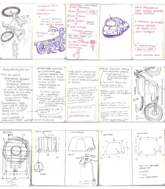
Here are some scans of my note book to date:


Week 4 - Modeling and Experimentation


Summary of Tasks Completed

- This week I began modeling in Solidworks. As a group we decided to delegate each member with a single part of the motorbike that we deemed to be of high importance. I chose to do the swing arm. As I am relatively unfamiliar with the program it did take me a long time to make significant progress. Also, measuring the object can be very difficult as there are curves and thicknesses that are hard to define. To help me gain accuracy I used a Caliper. Overall, I believe the final model is as accurate as can be, although as a group we have allowed a 2 mm tolerance. 

Here is an image during the modeling stage. Note: this is not the final model.


Experiment and research on Kinect for modeling


As we are Architectural computing students, we aim to use as many new and helpful technologies as possible throughout the process of our assignment. During class this week we borrowed a Microsoft Kinect to aid our 3D modelling process by gaining measurements and shapes of curves that otherwise we would be unable to gain accurate measurements of.

During our experimentation with the Kinect, we experiemented with different postiions of the kinect as well as distances away from the model, to establish the most accurate way to model the featherbed frame. As you can see in the video our tech methods of placing a box and cardboad as a stand on a spinning chair was the best we could come up with to maintain the one smooth rotational axis.  The results of the frame model can be seen in the photo documentation underneath, and some screen captures of the Kinect modelling process can be seen in the videos and photos below.

Video Documentation


Photo Documentation


Overall the process of modelling with the Kinect was successful and was a fun process to learn about. However when you compare its results to the photo stitching results we had completed the week before, it came in 2nd. The photo stitching model had fewer errors in the model, as well as had the ability to texture the model, which the Kinect system does not have.


Week 3 - Honda Deconstruction - CAD drawings


Summary of tasks completed

- Deconstruction of Honda CB750 motorcycle - as a group we helped deconstruct the Honda CB750 motorcycle in order to get a bit of a better understanding of the bike and its parts. We placed all of the parts into organised boxes and moved them from an off site garage, into a office room within the university in order to gain better access to the parts. I brought in my GoPro to document this process which will be placed on our Wiki and may become helpful when we reconstruct the bike to test our designed brackets that will support the new engine.

- Our team has developed various platforms for communication, presentation and file sharing. This includes individual blogs (individual presentation and progress), a facebook group (team communication), wiki (group presentation and progress) and dropbox (file sharing). 


Check out our wiki progress at: www.shadesofblack.wikispaces.com


- I drew up a measured drawing in AutoCAD of the Honda CB750 motorbike frame using the manuals drawing and my own measurements as reference. 


- I developed a sample 'Shades of Black' format that may be used for our Wiki style layout. 


- Watched tutorials and began playing with SolidWorks. I found the best and most useful tutorials were actually the ones within the Solidworks program. These tutorials cover a wide range of tools and tasks and range from Introductory to Skilled. 


Video Documentation


Photo Documentation


The group also experimented with Photostitching as a method of creating an accurate base model of parts that would be too hard to accurately measure.  This involved taking various photos of an object (the engine) from all angles and placing it in a program called Autodesk 123D Catch which stitches the photos together using reference points to form a mass geometry. Here are a few images of some renders Dan and Alex got out of the photostitched model.